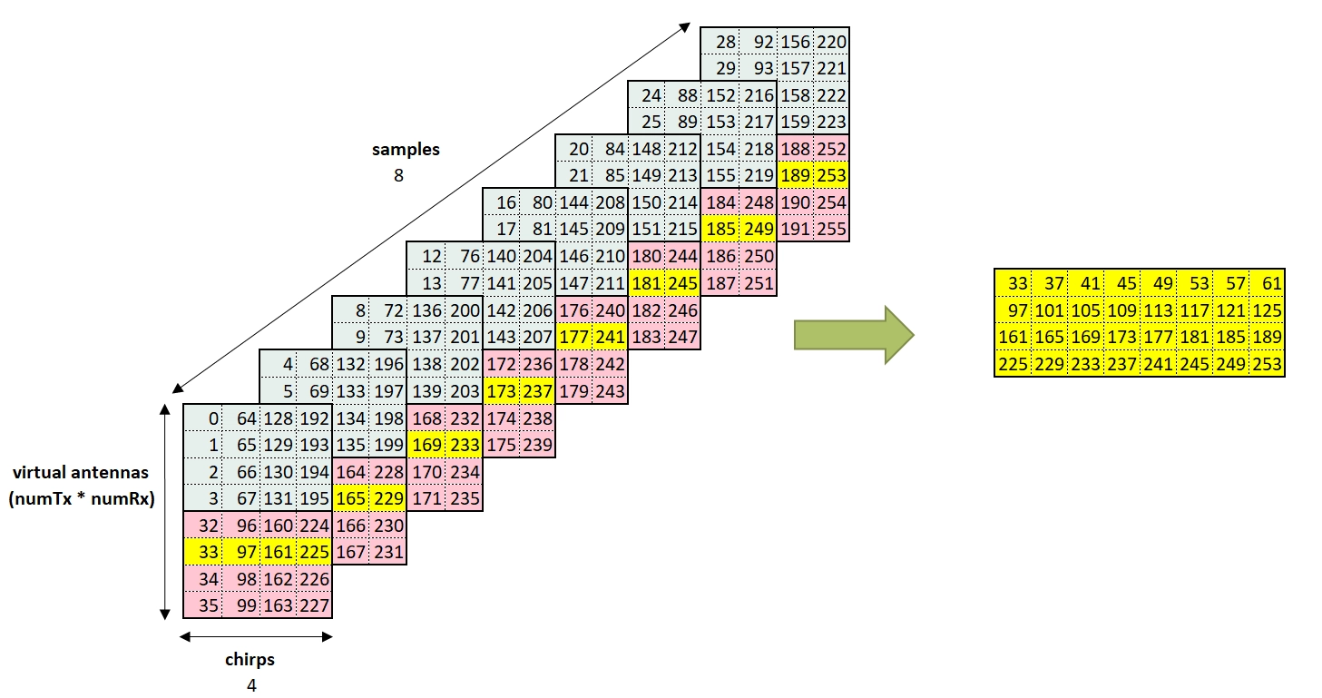
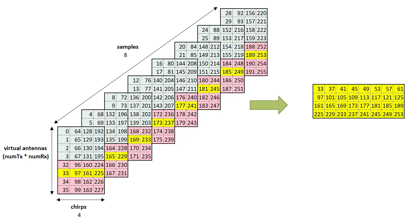
【一】英飞凌毫米波雷达接收数据的格式
4/28/2026 | 5 minutes to read | Tags: 雷达信号处理, FMCW雷达, 英飞凌
测量帧
一个测量帧中包含的时域信号以cube data structure的形式(3维向量)获取。
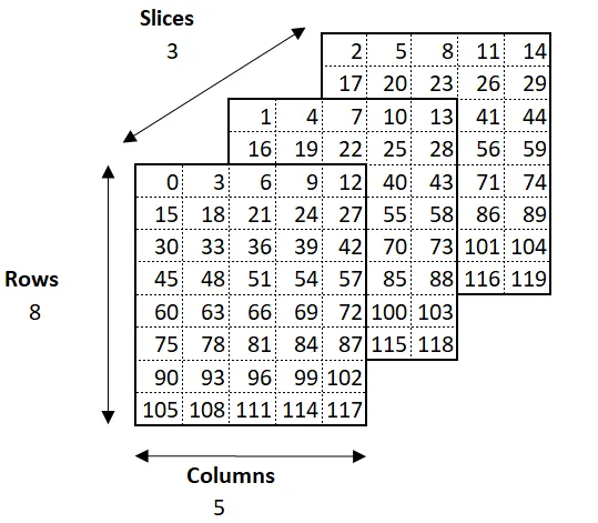
| ifx_Cube_R_t | Frame dimensions |
|---|---|
| Rows | Number of Rx antennas for each active Tx antenna available in the device |
| Columns | Number of chirps configured in a frame |
| Slices | Number of samples per chirp |
雷达接收到的原信号随后就会转换成ifx_Cube_R_t这样的数据结构。
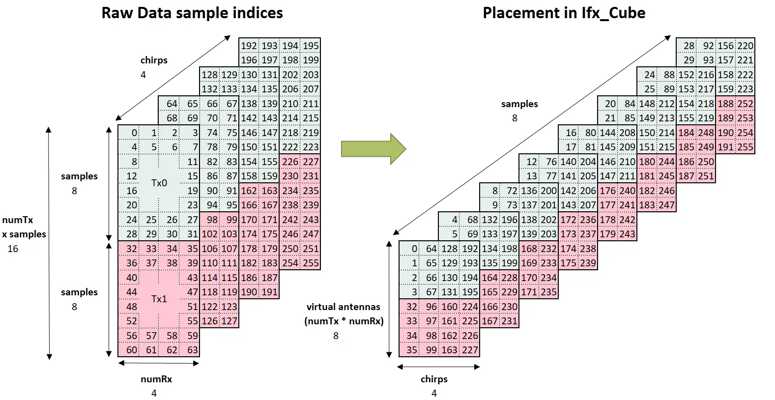
虚拟Rx天线排布
假设发射天线TX=2,接收天线RX=4,那么总共有8个虚拟Rx。
| Virtual Antenna Index | TX 1 | TX 2 | RX 1 | RX 2 | RX 3 | RX 4 |
|---|---|---|---|---|---|---|
| 0 | X | X | ||||
| 1 | X | X | ||||
| 2 | X | X | ||||
| 3 | X | X | ||||
| 4 | X | X | ||||
| 5 | X | X | ||||
| 6 | X | X | ||||
| 7 | X | X |
假如我们要从一个天线中取出数据,比如第5个虚拟天线,使用ifx_Cube_R_t数据结构,就只需要取第6行的数据即可拼成这个天线接收到的所有数据。
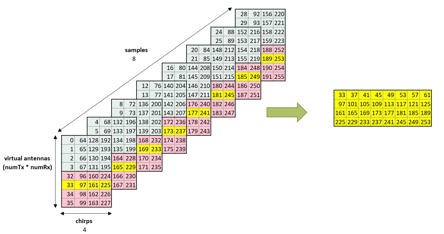
上图展示了将单个天线接收到的数据提取为矩阵的过程。
使用英飞凌SDK实现
配置雷达参数
根据[[FMCW0雷达信号处理]]中的内容,配置好雷达的参数并应用于雷达。
使用with DeviceFmcw() as device:寻找设备并选定设备,后续配置参数使用device即可。
config = FmcwSimpleSequenceConfig(    frame_repetition_time_s=307.325e-3,  # Frame repetition time    chirp_repetition_time_s=500e-6,  # Chirp repetition time    num_chirps=16,  # chirps per frame    tdm_mimo=False,  # set True to enable MIMO mode, which is only valid for sensors with 2 Tx antennas    chirp=FmcwSequenceChirp(        start_frequency_Hz=59e9,  # start RF frequency, where Tx is ON        end_frequency_Hz=61e9,  # stop RF frequency, where Tx is OFF        sample_rate_Hz=2e6,  # ADC sample rate        num_samples=128,  # samples per chirp        rx_mask=1,  # RX mask is a 4-bit, each bit set enables that RX e.g. [1,3,7,15]        tx_mask=1,  # TX antenna mask is a 2-bit (use value 3 for MIMO)        tx_power_level=31,  # TX power level of 31        lp_cutoff_Hz=500000,  # Anti-aliasing filter cutoff frequency, select value from data-sheet        hp_cutoff_Hz=80000,  # High-pass filter cutoff frequency, select value from data-sheet        if_gain_dB=30,  # IF-gain    ),)
with DeviceFmcw() as device:    # set device configuration for presence sensing    sequence = device.create_simple_sequence(config)    device.set_acquisition_sequence(sequence)
    frame_contents = device.get_next_frame()    print(np.shape(frame_contents)) # (1, 1, 16, 128)
如果需要提取配置参数,使用config即可。
print(config)# FmcwSimpleSequenceConfig: # frame_repetition_time_s: 0.30732500553131104 # chirp_repetition_time_s: 0.0005000000237487257 # num_chirps: 16 # tdm_mimo: False # chirp: FmcwSequenceChirp: # start_frequency_Hz: 59000000000.0 # end_frequency_Hz: 61000000000.0 # sample_rate_Hz: 2000000.0 # num_samples: 128 # rx_mask: 1 # tx_mask: 1 # tx_power_level: 31 # lp_cutoff_Hz: 500000 # hp_cutoff_Hz: 80000 # if_gain_dB: 30得到的frame_contents中第0维一直都是1(可以squeeze掉),第1维表示接收的天线,如果用到了两根天线第一维的shape就为2。第2维和第3维分别表示chirps(慢时间)和sample(快时间)。
我们设置了rx_mask=1,因此只用到了一根天线,利用下面代码即可得到数据:
frame_contents_squeezed = np.squeeze(frame_contents, 0)print(np.shape(frame_contents_squeezed)) #(1, 16, 128)mat = frame_contents_squeezed[0, :, :]print(np.shape(mat)) # (16, 128)接下来就可以进行距离检测了。
参考文献
Infineon RFS SDK Documentation中Radar device configuration parameters部分内容。
← Back to blog